Volt Motor Wiring Diagram
Volt Motor Wiring Diagram. WIRING DIAGRAM A wiring diagram shows, as closely as possible, the actual location of all component parts of the device. Internal Wiring Diagrams of Small and Fractional Horsepower Electric Motors.
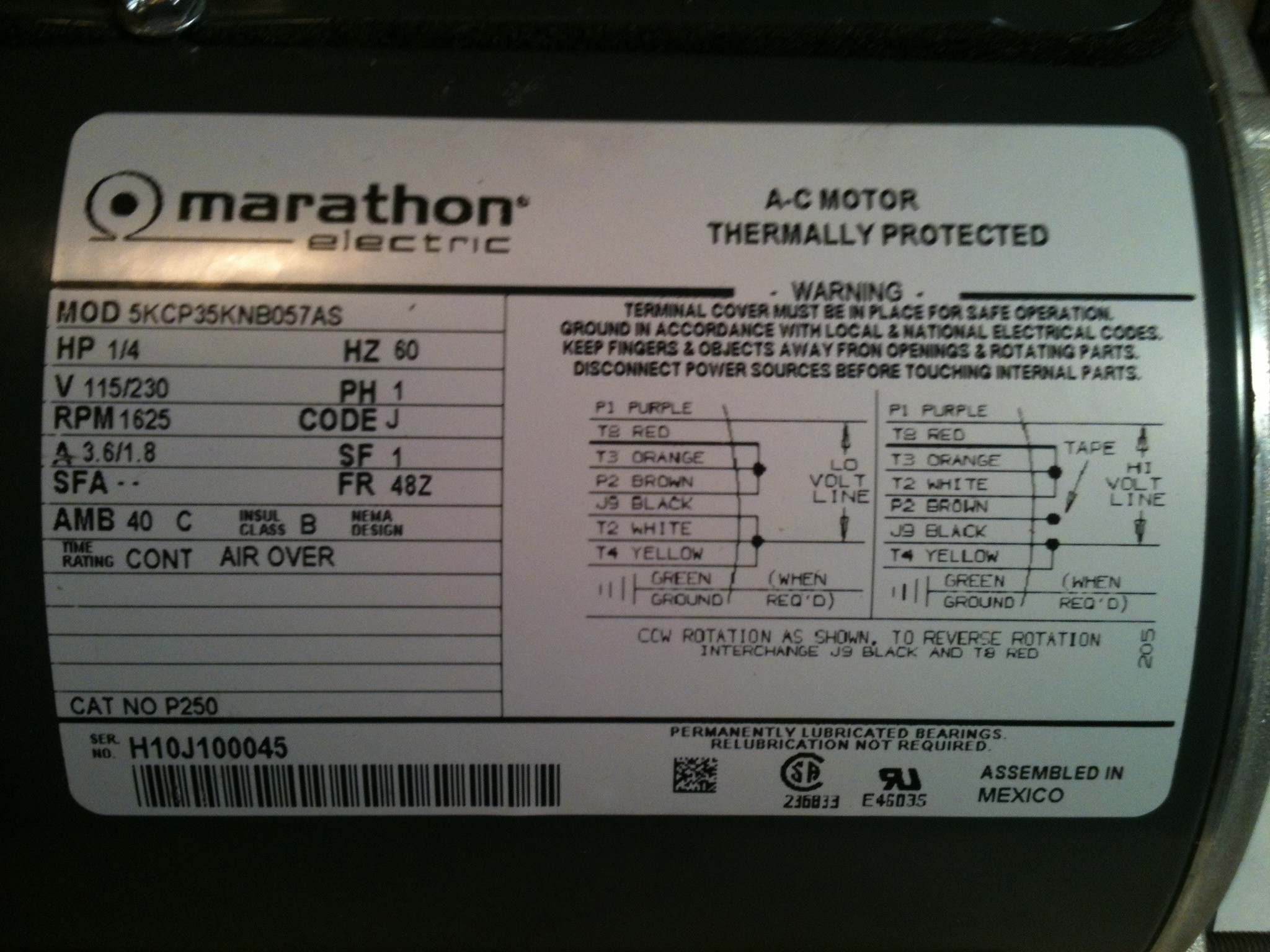
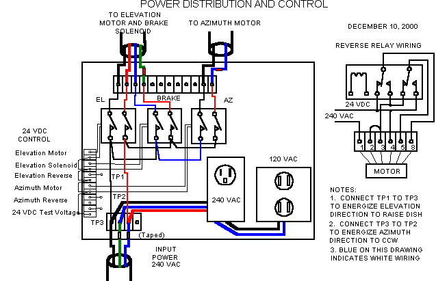
WIRING DIAGRAM A wiring diagram shows, as closely as possible, the actual location of all component parts of the device.
With ammeter shown in optional position, note that − and + symbols are reversed.

Find Out Here Minn Kota Maxxum 74 Wiring Diagram Sample

4 Pole Starter solenoid Wiring Diagram | Free Wiring Diagram
Picture10

480 Volt Motor Wiring Diagram - Wiring Diagram Networks

Motor Wiring Diagrams | Groschopp

12 Volt Relay Wiring Diagram | Free Wiring Diagram

24 Volt Trolling Motor Wiring Diagram | Fuse Box And ...

Minn Kota Maxxum 74 Wiring Diagram Gallery

220 To 110 Wiring Diagram - Wiring Forums
Watch till the end for my Tech Tip. Motor - A Motor represents a transducer by which electrical energy gets converted to kinetic energy. A DC motor has two input terminals, one positive and one negative.

0 Response to "Volt Motor Wiring Diagram"
Post a Comment