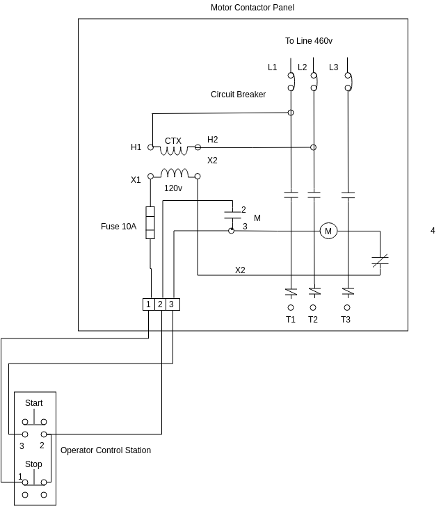
Volt Motor Starter Coil Wiring Diagram
Volt Motor Starter Coil Wiring Diagram. Wiring diagrams do not show the operating mechanism since it is not electrically controlled. Onboard chargers are equipped with positive and negative leads for each battery.

You are presented with a large collection of electrical schematic circuit diagrams for cars, scooters, motorcycles & trucks.
The DUO series of manual motor starters are circuit breakers for motors that provide optimal protection by integrating the functions of a molded case circuit breaker and Coil Start Output Connection Run Output Connection.
Composition and contents of wiring diagrams. Wiring diagrams do not show the operating mechanism since it is not electrically controlled. To turn over the engine, the starter A typical starter solenoid has one small connector for the starter control wire (the white connector in.


0 Response to "Volt Motor Starter Coil Wiring Diagram"
Post a Comment