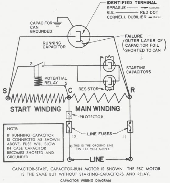
Volt Capacitor Wiring Diagram
Volt Capacitor Wiring Diagram. It shows how a electrical wires are interconnected which enable it to also show where fixtures and components might be coupled to the system. HOW T O READ THE WIRING DIAGRAMS Contents of Wiring Diagrams.

So that if you don't have a Capacitance meter, still you can test the capacitors.
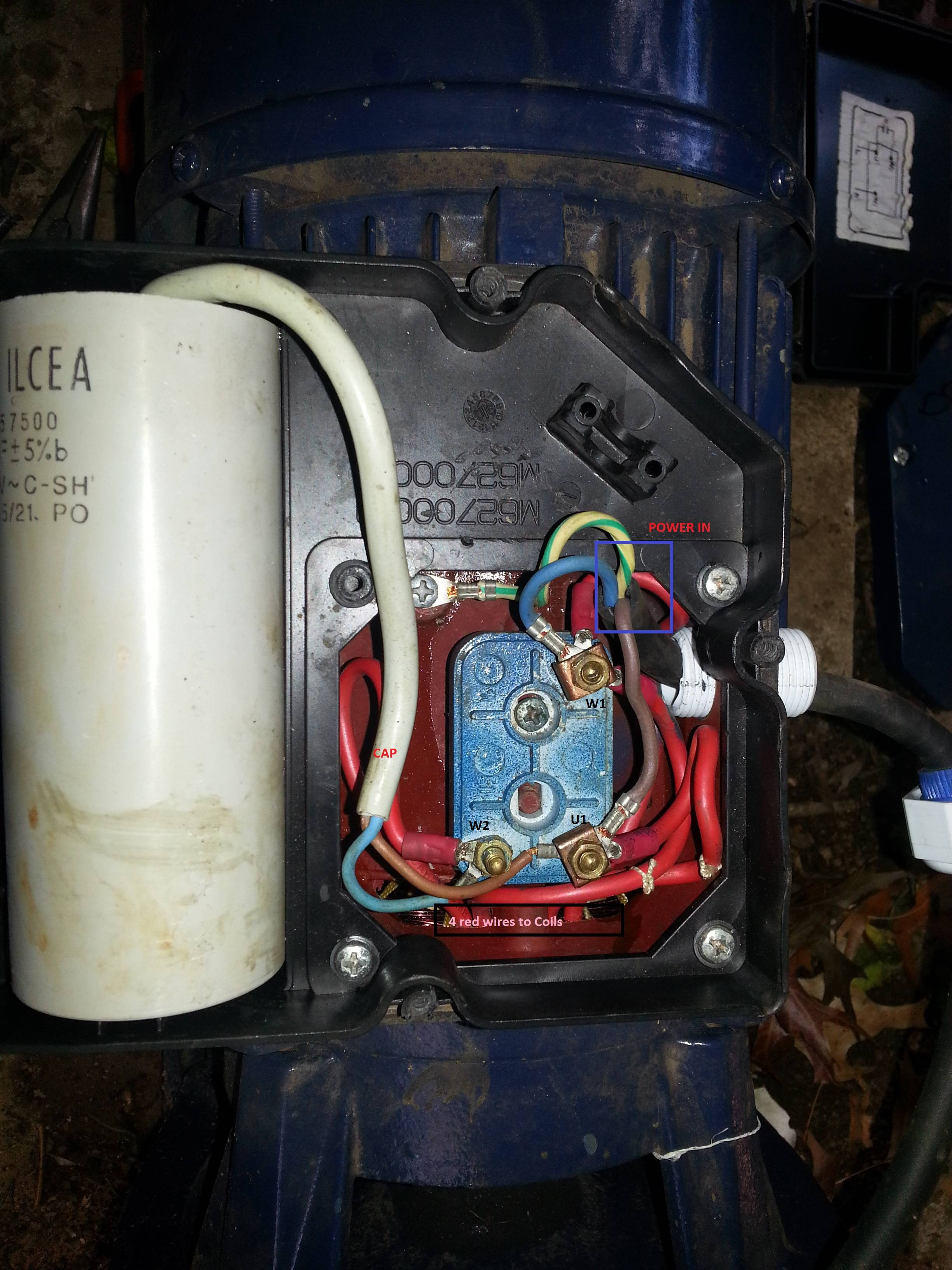
Either wire will connect to either side of the capacitor and will work fine.
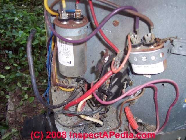
Electric Motor Starting Capacitor Wiring & Installation
Wiring Diagram Compressor Capacitor Start Capacitor Run ...

GlassWolf's Pages
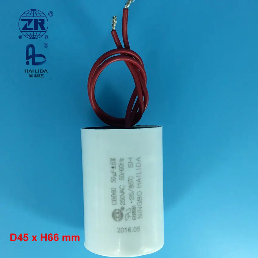
250 Volts Motor Capacitor Ac Wiring Diagram 50uf - Buy 250 ...
UK Vintage Radio Repair and Restoration - High Voltage ...
What Is A Grounded Hermetic Pressor Motor - Tips Cepat
Single Phase Motor Wiring Diagram With Capacitor Start ...

28 Ac Motor Start Capacitor Wiring Diagram - Wiring ...

Furnace Air Handler HVAC Direct Drive Blower Motor 1/3 HP ...
Make sure that the capacitor does not have positive or negative on the terminals. Each part should be placed and linked to other. This is an exclusive section available only to our members.

0 Response to "Volt Capacitor Wiring Diagram"
Post a Comment