V Phase Wiring Diagram Picture
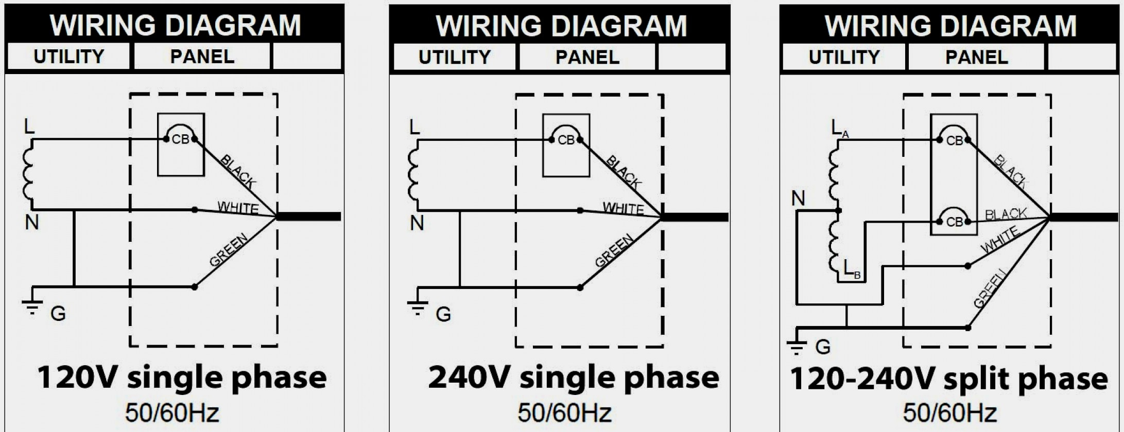
V Phase Wiring Diagram Picture. If I connect the phase wire at the drain pin of "HO MOSFET" then. WIRING DIAGRAM A wiring diagram shows, as closely as possible, the actual location of all component parts of the device.

It shows the components of the circuit as simplified shapes, and the gift and signal friends amongst the.
The above diagram shows the GFCI wiring to Multiple Outlet as in white while the pictures are same.

Electrical Page: Single Phase Motor Contactor Wiring Diagram
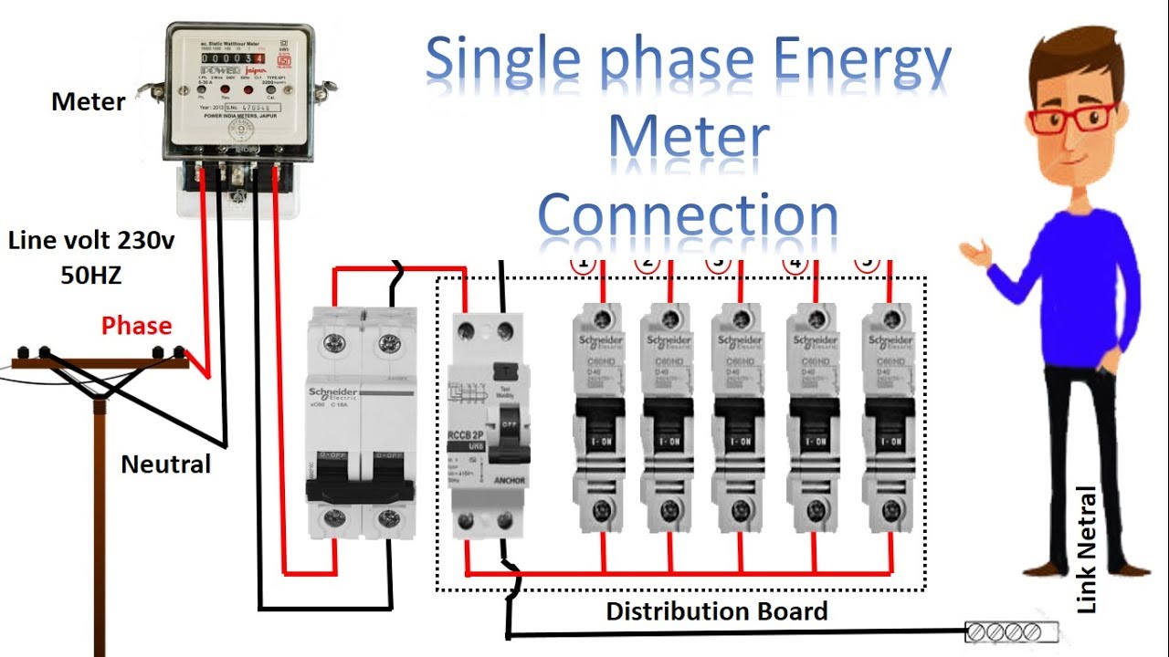
Single Phase Transformer Wiring Diagram | Wiring Diagram
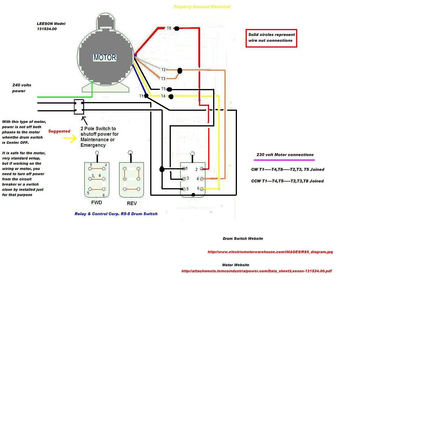
Wiring Diagram For 230V Single Phase Motor | Wiring Diagram

3 Phase 240V Motor Wiring Diagram - Wiring Diagram And ...
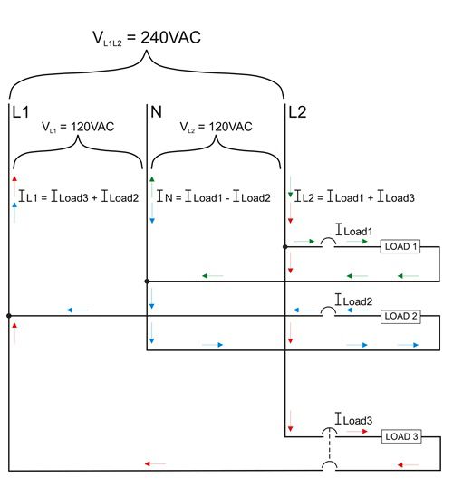
A Single Phase 240 Volt Breaker Wiring Diagram - Wiring ...

Wiring Diagram For 220 Volt Single Phase Motor ...
230 Volt Single Phase Motor Wiring Diagram - Database ...

A Single Phase 240 Volt Breaker Wiring Diagram - Wiring ...
A Single Phase 240 Volt Breaker Wiring Diagram - Wiring ...
For Remove wire "C" if the contactor coil is to operate separate control voltage source, remove jumpers on a voltage other than line voltage or in a separate "A" and "B" and connect. A wiring diagram is a simple visual representation of the physical connections and physical layout of an electrical system or circuit. Some HONDA Civic Wiring Diagrams are above the page.

0 Response to "V Phase Wiring Diagram Picture"
Post a Comment