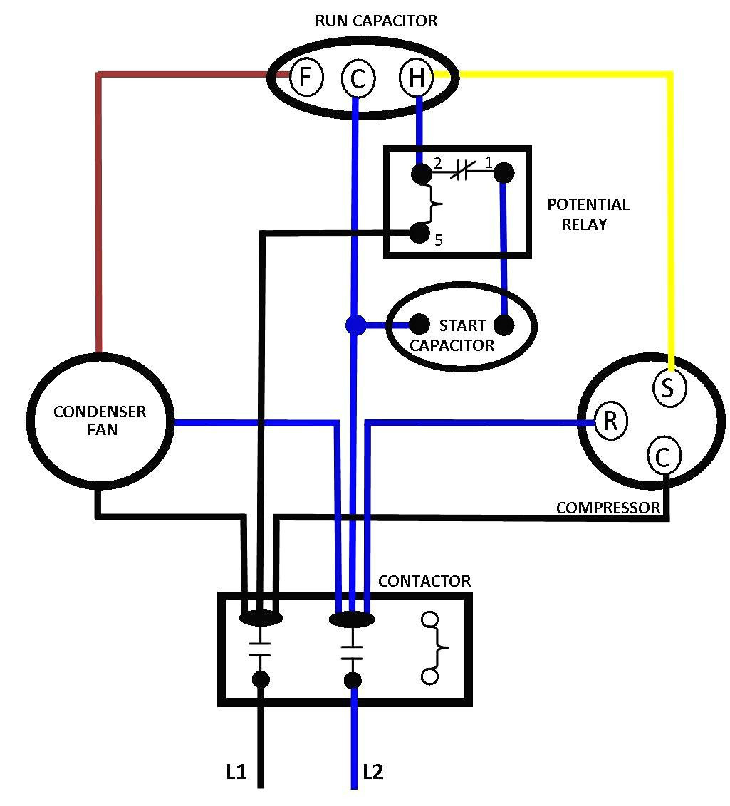
Volt Wiring Diagram Single Phase
Volt Wiring Diagram Single Phase. Single Phase Motor Internal Wiring Diagrams. The post discusses a single phase variable frequency drive circuit or a VFD circuit for controlling AC The above settings will determine the correct volts per Hertz (V/Hz) for the particular motor.

The diagram below shows the wiring for a single phase motor and the path through the contactor and overload NOTE : These notes and diagrams provide a schematic method of achieving the control but it remains the responsibility of the installer to ensure that any safety requirements, local legislation.
In electrical engineering, single-phase electric power is the distribution of alternating current electric power using a system in which all the voltages of the supply vary in unison.
Single phase capacitor sizing - Electrical Engineering Centre. When install a motor using capacitor for starting or running methods,we must sizing the rated of capacitor suitable with motor to get correct starting torque and avoid winding from overheating and. As no starter is used in the case of electronic ballast application, the wiring diagram is slightly different.


0 Response to "Volt Wiring Diagram Single Phase"
Post a Comment