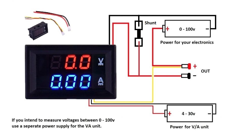
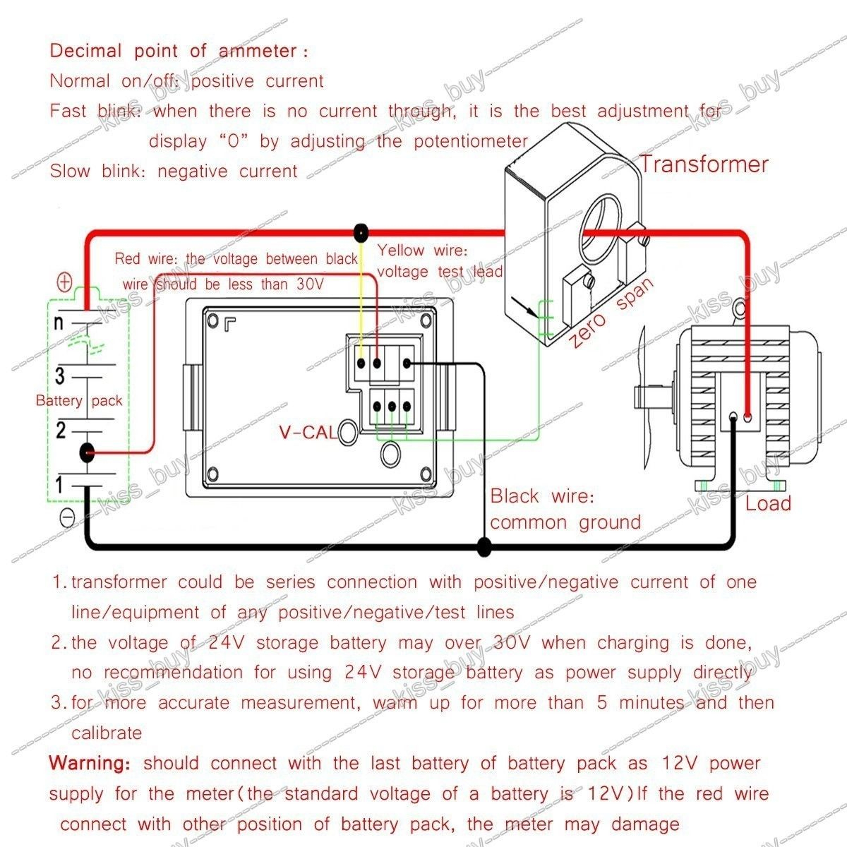
Volt Voltmeter Wiring Diagram
Volt Voltmeter Wiring Diagram. Now after images, and panel meter company diagram, i am gonna to share I hope after viewing voltmeter ammeter, hz meter wiring diagram, you will completely understood, now i you have any question regarding this post the. Different types of voltmeters include analog voltmeters with moving coil instruments, VTVMs and FET Voltmeters and digital voltmeters with A/D converters.

If a Half wave rectifier is connected ahead of DC voltmeter, then that entire combination together is called AC voltmeter using Half wave rectifier.
There is a "wiring diagram" and adjacent to it a In a case like this, it is advisable to use relays having coils which operate at a very small value of volt-amperes.
Thus, disturb the reading of the voltmeter. Before using a voltmeter for the first time, learn how to set the device correctly, and test it out on a low-voltage circuit such as a. With some voltmeters, one must make sure that the wires are connected to the right spots: the positive connection on the voltmeter to the more positive "part" of the voltage source There are two kinds of voltmeters.


0 Response to "Volt Voltmeter Wiring Diagram"
Post a Comment