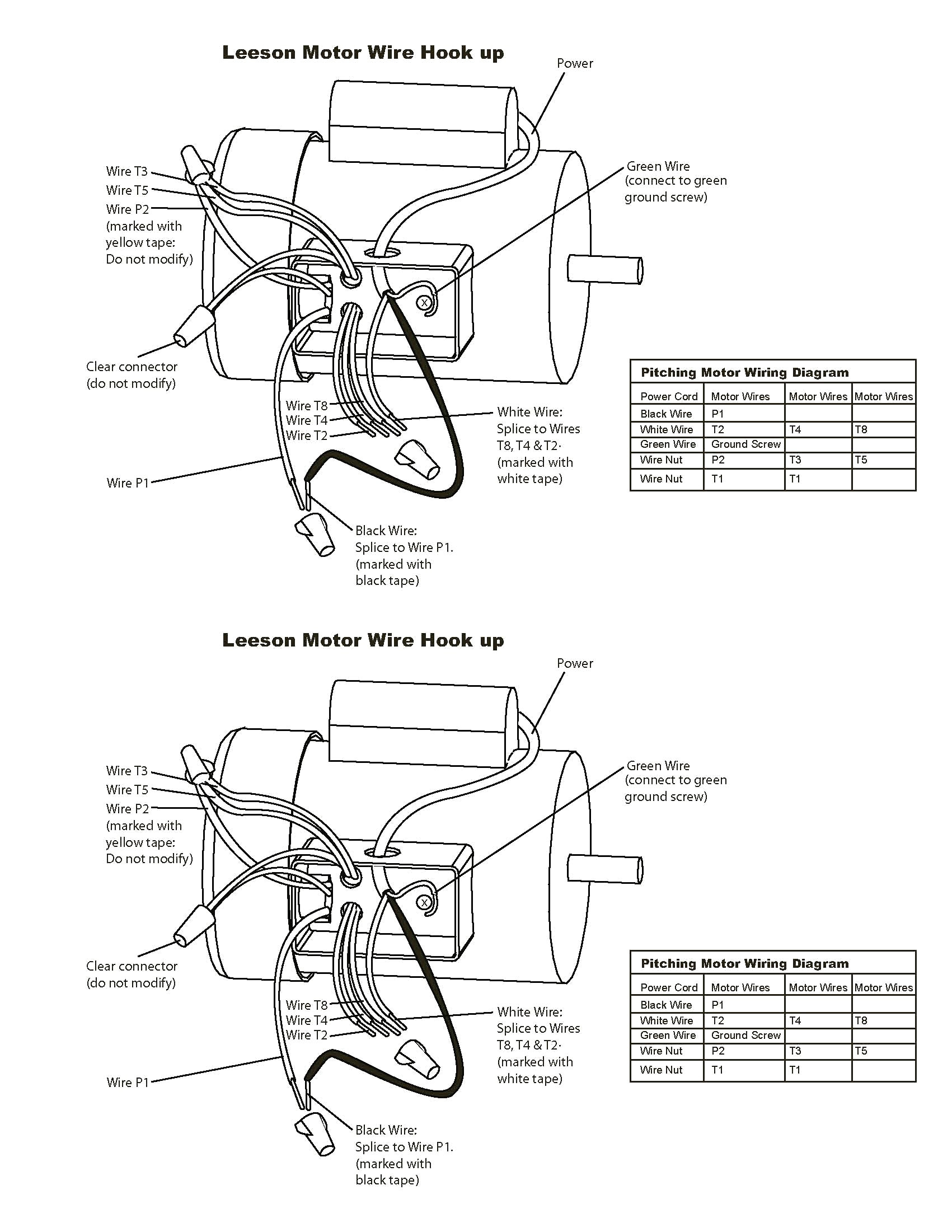
To V Single Phase Wiring Diagram

To V Single Phase Wiring Diagram. If starter is used on lower voltage, connect per coil diagram. The diagram below shows the wiring for a single phase motor and the path through the contactor and overload NOTE : These notes and diagrams provide a schematic method of achieving the control but it remains the responsibility of the installer to ensure that any safety requirements, local legislation.

Air Compressor Magnetic Starters | mastertoolrepair.com
Air Compressor Magnetic Starters | mastertoolrepair.com (Ricky Fitzgerald)
How electricity. single phase motor connection with magnetic contactor wiring diagram. On the other hand, this diagram is a simplified variant of this arrangement. There is a "wiring diagram" and adjacent to it a "line diagram." starting and protecting small, single phase, two-. is mounted in the same enclosure to allow.

For all other SINGLE-PHASE wiring diagrams refer to the manufacturers data on the motor.

How electricity. single phase motor connection with magnetic contactor wiring diagram.

Wiring single phase electric motor to mains electricity?

220v Single Phase Wiring Diagram

Baldor Motors Wiring Diagram Collection | Wiring Diagram ...

Help on wiring a drum Switch to a single phase 230v motor

3 Phase Electric Motor Starter Wiring Diagram | Free ...

Single Phase Motor Wiring Diagram With Capacitor Start ...

3 Phase Magnetic Motor Starter and Wire Diagram - YouTube

Atlas® Air Force AF7 Two Stage 5 HP. 220 Volt Single Phase ...

The complete guide of single phase motor wiring with ...

Refer to the flowchart and basic configuration diagram provided below to understand the procedures and installation methods to. In this video we learn electrical engineering basics by learning single phase meter wiring diagram. If starter is used on lower voltage, connect per coil diagram.

Subscribe to receive free email updates:

0 Response to "To V Single Phase Wiring Diagram"

Post a Comment