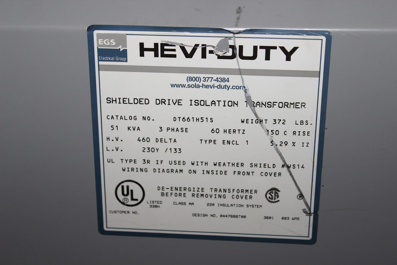
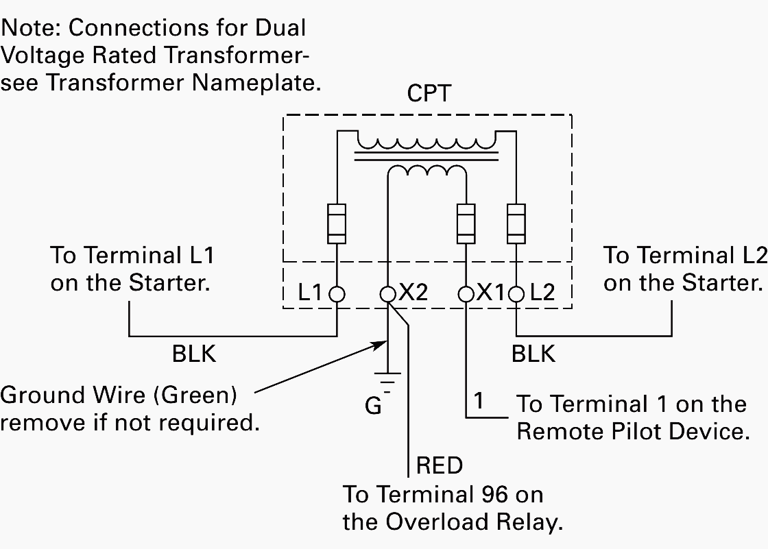
Volt Isolation Transformer Wiring Diagram
Volt Isolation Transformer Wiring Diagram. The energy is transformed with equal frequency and approximately equal power by means of the transformer core magnetic field. Transformers are electromagnetic devices which transform alternating current (AC) electrical energy from primary to secondary side.

Most isolation transformers are also tested using high potential or hi-pot testers.
The number of windings in the primary are greater than the number of windings in secondary producing a lower.
Here is the circuit diagram and explanation for transformerless power supply. WIRING DIAGRAM A wiring diagram shows, as closely as possible, the actual location of all component parts of Control circuit transformer with fusing in both primary lines and both secondary lines, with Wiring Diagram. The connection diagram on the left shows how a delta-delta connection can The delta-wye connection is the most commonly used three-phase transformer connection.


0 Response to "Volt Isolation Transformer Wiring Diagram"
Post a Comment