V Transformer Wiring Diagram
V Transformer Wiring Diagram. The first element is emblem that indicate electrical element from the circuit. Transformer Basics and the Transformer Principals of Operation as how a Single Phase Transformer Generates a Transformer Basics.
A varying current in any one coil of the transformer produces a varying.
Transformers are delivered in an unconnected condition and must be configured for the system need.
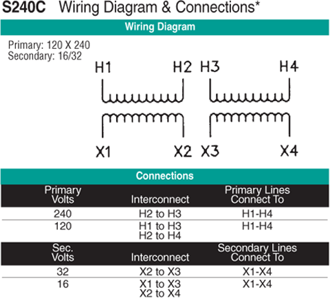
1.5 KVA Transformer Primary 120x240 Secondary 16/32 ...
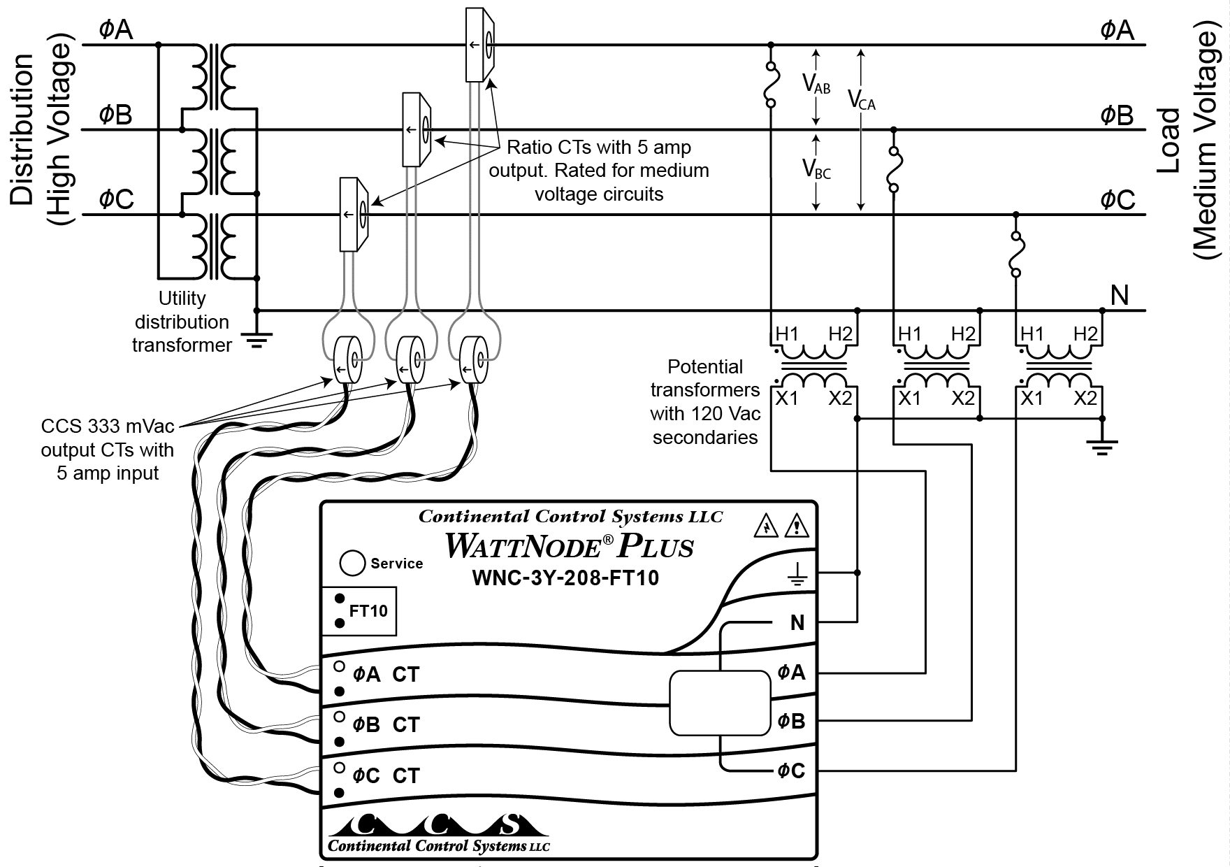
Using Potential Transformers - Continental Control Systems ...
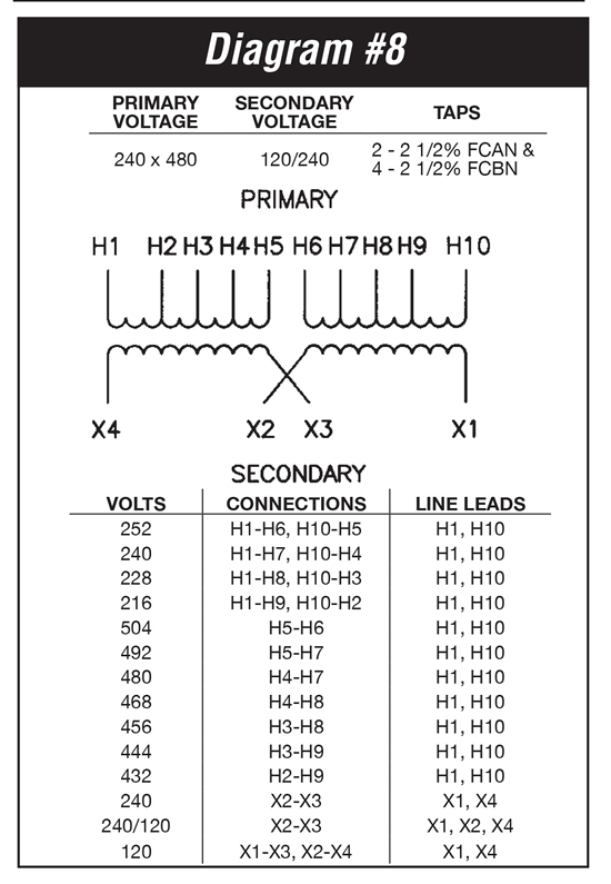
37.5 KVA Transformer Primary 240x480 Secondary 120/240 ...
Step Up Transformer 208 to 480 Wiring Diagram Gallery
70 Volt Speaker Transformer Wiring Diagram - Collection ...
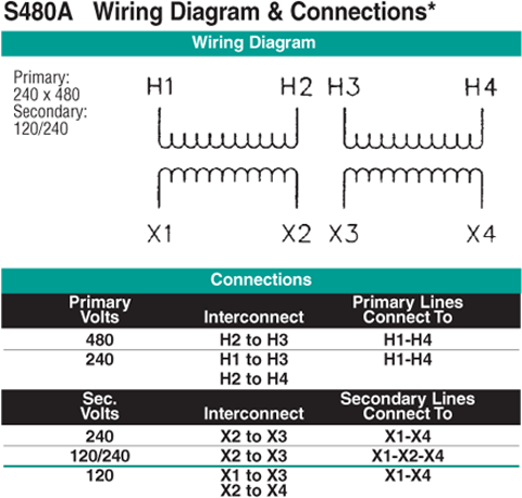
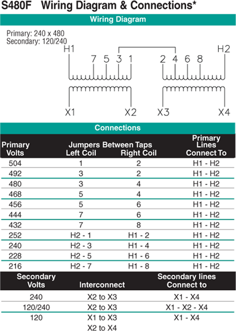
1.5 KVA Transformer Primary 240x480 Secondary 120/240 ...
Motor Starter Wiring Diagram With 480V 3 Phase Input To ...
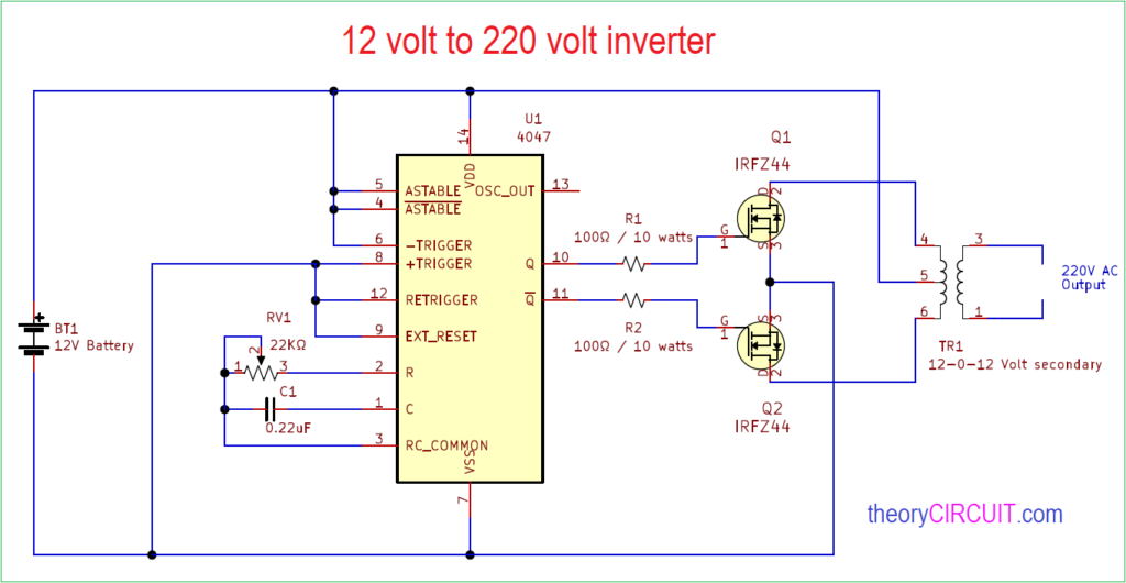
12 Volt to 220 Volt Inverter
120V/24V Transformer for Brooders | Hog Slat
Issue: Single Phase Transformer Primary and Secondary wiring. The first element is emblem that indicate electrical element from the circuit. Whatever you are, we attempt to bring the content that matches exactly what you are trying to find.

0 Response to "V Transformer Wiring Diagram"
Post a Comment